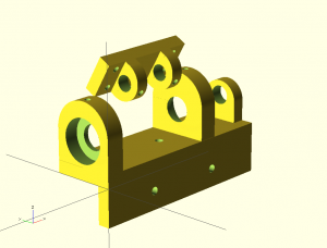
While assembling my new dual motor test jig I realized that my drill press manufacturing tolerances were too loose to ensure reliable operation. Then it struck me that a 3D printed part would give me the required tolerances; as well it would easily allow me to add actual bearings. I have set out in a new direction by designing printed parts using OpenSCAD. The latest test jig now consists of two printed parts that form a pivot for the swing arm and a bearing support to hold everything down. For the bearing I use a 608 roller skate bearing with an 8mm shaft which is connected to a potentiometer. The bearing support provides a recess to hold each of the 608 bearings while a 3mm set screw locks each bearing in place. The support on the far right allows a potentiometer to be mounted so that the arm angle can be measured with an A/D converter. The connection between the 8mm shaft and the 0.25″ potentiometer shaft is made using heat shrink which ties the two assemblies together. The pivot is designed to be bolted to the swing arm with 4mm bolts. The axle is made of 8mm steel with flat spots ground on it to allow the 2 set screws to lock the axle and pivot together. This ensures the potentiometer actually measures the angle of the swing arm.
The design file illustrates both parts and I have attached the code to the post. This is a work in progress and the parts are to be delivered Sept 5th. Hopefully I can get the jig assembled before the next Ottawa Robotics meeting mid-Sept.
Use Ctrl + to zoom
Quadracopter Quad_Pivot_Brace.scad
//Quadracopter Quad_Pivot_Brace.scad
//Copyright Doug Commons 2012
//This is the pivot brace for the quadracopter test jig
//Print this file using imperial inch scale

$fn = 200;
Thickness = 0.25;
Width = 2.0;
Depth = 0.75;
Shaft = 8/25.4;								                //608 bearing

module Pivot(){
difference(){
	union(){
		translate ([Width*0.27,0,0])Brace();
		translate ([Width*0.73,0,0])Brace();
		cube([Width,Depth,Thickness]);
	}
	translate ([0.25,(Depth-7/16)/2,-0.5])cylinder(r=0.0625,h=1);			//base drill#1
	translate ([0.25,Depth-(Depth-7/16)/2,-0.5])cylinder(r=0.0625,h=1);		//base drill#2

	translate ([Width-0.25,(Depth-7/16)/2,-0.5])cylinder(r=0.0625,h=1);		//base drill#3
	translate ([Width-0.25,Depth-(Depth-7/16)/2,-0.5])cylinder(r=0.0625,h=1);	//base drill#4
}
}

module Brace(){
	translate([Thickness /2,0,0])rotate([0,-90,0])					//Center
	difference(){
		union(){
			translate ([0.375,Depth/2,0])cylinder(r=Depth/2,h=Thickness);	//Curved top
			translate ([0,0,0])cube([0.375,Depth,Thickness]);		// support
		}
		translate ([0.4375,Depth/2,-0.5])cylinder(r=Shaft/2,h=1);		//Shaft
		translate ([0.5,Depth/2,Thickness/2])rotate([0,90,0])cylinder(r=0.0625,h=1);//Key
	}
}

Pivot();
Quadracopter test jig Quad_test_jig.scad
//Quadracopter test jig Quad_test_jig.scad
//Copyright Doug Commons 2012
//This is the bearing support for the quadracopter test jig
//Print this file using metric millimeter scale
//Set screws are 3mm
//Mounting holes are 4mm
//Bearings are 608 roller skate bearings which are 22x7mm with an 8mm shaft

$fn = 100;
Thickness = 0.25*25.4;						//Mounting flange and base thickness
Bearing = 0.375*25.4;						//Bearing support width
Height = 1.5*25.4;						//
Depth = 1.25*25.4;						//Depth of the base
Pot = 0.75*25.4;						//Width of potentiometer support
AxleWidth = 2.5*25.4;						//Distance between bearing supports
TotalWidth = 4.0*25.4;						//Total width of base

module Quad(){
difference(){
	union(){
		translate ([0,Depth/2,Height-Depth/2])HalfCircle();
		translate ([0,0,0])cube([Bearing,Depth,Height-Depth/2]);		//left support
		translate ([AxleWidth,Depth/2,Height-Depth/2])HalfCircle();
		translate ([AxleWidth,0,0])cube([Bearing,Depth,Height-Depth/2]);	//right support
		translate ([TotalWidth-Thickness,Depth/2,Height*.7-Pot/2])PotHalfCircle();
		translate ([TotalWidth-Thickness,(Depth-Pot)/2,0])cube([Thickness,Pot,Height*0.7-Pot/2]);//potentiometer support
		translate ([0,0,-0.75*25.4])cube([TotalWidth,Thickness,0.75*25.4]);	//flange
		translate ([0,0,0])cube([TotalWidth,Depth,Thickness]);		        //base
	}
	translate ([-0.5,Depth/2,Height/2])rotate([0,90,0])cylinder(r=22/2,h=7.5);	//bearing #1
	translate ([7/2,Depth/2,Height/2])cylinder(r=1.5,h=Height);			//set screw
	translate ([AxleWidth+Bearing-7,Depth/2,Height/2])rotate([0,90,0])cylinder(r=22/2,h=7.5); //bearing #2
	translate ([AxleWidth+Bearing-7/2,Depth/2,Height/2])cylinder(r=1.5,h=Height);	//set screw

	translate ([AxleWidth*0.3,Depth/2,-0.5])cylinder(r=2,h=Thickness+1);		//base drill#1
	translate ([Thickness+AxleWidth*0.7,Depth/2,-0.5])cylinder(r=2,h=Thickness+1);  //base drill#2

	translate ([0.3*TotalWidth,Thickness+0.5,-0.375*25.4])rotate([90,0,0])cylinder(r=2,h=Thickness+1);//flange drill#1
	translate ([0.7*TotalWidth,Thickness+0.5,-0.375*25.4])rotate([90,0,0])cylinder(r=2,h=Thickness+1);//flange drill#2

	translate ([-0.5,Depth/2,Height/2])rotate([0,90,0])cylinder(r=4*25.4/16,h=TotalWidth-10);//axle clearance
//	translate ([-0.5,Depth/2,Height/2])rotate([0,90,0])cylinder(r=22/2,h=TotalWidth-10);	//axle
	translate ([TotalWidth-Thickness-0.5,Depth/2,Height/2])rotate([0,90,0])cylinder(r=3*25.4/16,h=Thickness+1);//axle
}
}

module HalfCircle(){
	difference(){
		translate ([0,0,0])rotate([0,90,0])cylinder(r=Depth/2,h=Bearing);	//axle
		translate ([-1.,-(Depth+1)/2,-(Depth+1)/2])cube([Thickness+2,Depth+1,(Depth+1)/2]);
	}
}

module PotHalfCircle(){
	difference(){
		translate ([0,0,0])rotate([0,90,0])cylinder(r=Pot/2,h=Thickness);	//axle
		translate ([-1.,-(Pot+1)/2,-(Pot+1)/2])cube([Thickness+2,Pot+1,(Pot+1)/2]);
	}
}

Quad();
