I have been working on the AVR Mega48 IMU board and am slowly making progress however a few issues have cropped up and I am not happy with the implications. First the M48 processor acting as an I2C slave is very slow in responding to the LPC1769 processor requests. The M48 only runs at 8MHz when using the internal clock oscillator, so without adding a crystal I can’t speed the part up to its rated 20MHz performance. The slow speed of the I2C slave means that I have to slow down the LPC1769 transfers by adding delays to the I2C master code. Not only is the M48 access slow but by slowing the master I also effectively slow accesses to the accelerometer and gyroscope which is not at all desirable. To place it in context the current M48 I2C slave code has an access time of ~250us per byte compared with 10us for the gyroscope.
The slowness of the I2C access leads to a second problem which is the timing interaction between interrupt routines. The observed effect is that the I2C interrupt can add 250us of jitter to the pulse width modulator edges. In effect a quarter millisecond of edge jitter on the ESC pin will cause the motor speed to randomly jitter by 25%. This is a very difficult problem to resolve since I have three separate interrupts running on the M48. Unfortunately the AVR family does not support interrupt pre-emption that would have allowed for better control of the interrupt timing.
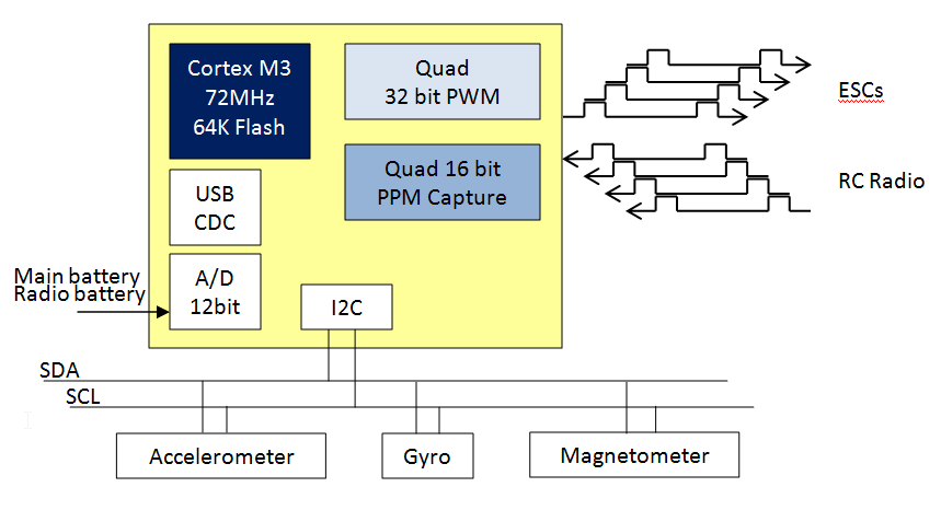
The question for me is; what is the value of writing a highly optimized and complex driver for the M48 when I could solve the problem with a better processor? I am leaning toward the hardware solution that replaces the M48 with an LPC1347 which is serious overkill, however, it offers a number of development advantages. First I get four 32 bit jitter free hardware PWM that can drive the ESCs and four 16 bit jitter free timer capture channels for measuring the radio signals. This additional hardware eliminates the timing interaction between software and the hardware driven timer. The second advantage is I have already written the code for the LPC1769 so this is a minor software port to run on the LPC1347. Finally the LPC1347 supports nested interrupts and programmable priority along with a 72MHz clock so the I2C slave timing will be 9 times faster than the AVR, which would solve the speed issue. There are smaller parts without USB that have the same performance however a USB interface really helps during development. The LPC1347 mass storage boot-loader allows me to load code without an in circuit programmer.
Features
LPC1347 processor – 72MHz ARM Cortex M3 with 64K Flash and 8K SRAM
4 channel 32 bit jitter free PWM for ESC motor control
4 channel 16 bit jitter free timer capture for reading RC radio signals
Accelerometer, Gyroscope and Magnetometer 9 degrees of freedom
Two battery monitor circuits
USB mass storage class provides Flash memory stick bootloader
The cost of doing this is the LPC1347 is twice the price of the Mega48 but at $5.50 it really doesn’t matter. I also need to layout a new PCB which will cost $10 for 10 boards at Seeed Studio. Finally there is the 3 week delay in waiting for boards to arrive. To keep moving forward I will re-use an LPCXpresso 1343 board to develop and test the code while waiting for the boards to arrive.
The schematic shows the LPC1347 wired to a USB mini connector. This was done to provide power and to allow code to be downloaded using the USB boot-loader that comes pre-installed on the chip. The bootloader looks like a 64K Flash memory stick when plugged into a host computer. The USB connector also allows me to write CDC serial software that can be used for diagnostics and control. The LPC1347 is a 3.3V device but it has 5V tolerant I/O so I can directly connect the radio PPM signals to the chip without level shifters. The 3.3V regulator provides power to the processor and is driven from either the 5V USB input or from the corner posts. Additionally the board is wire OR’d to the 5V/ground corner posts so that it can source or sink power from the board stack. Just like the M48 design, the processor will be an I2C slave providing access to the ESCs, radio, RGB LED and battery sub-systems. If you have followed this far you will also recognize that the LPC1347 could also act as the I2C master forming a complete 9DOF quadracopter controller on a board.
Schematic: LPC1347.pdf
