 As I experiment with the idea of flexible paper circuits I decided to try out a flex circuit material from http://www.conductiveinkjet.com/.The flexible circuit is available in 28cm wide sheets and the length determines the cost. The material costs ~$75/meter. To test out this material I designed a number of test circuits that could be printed including an ATTiny44 circuit that can be programmed with Arduino sketch. The material arrived this week and I have been learning how to deal with the materials unique mechanical properties.
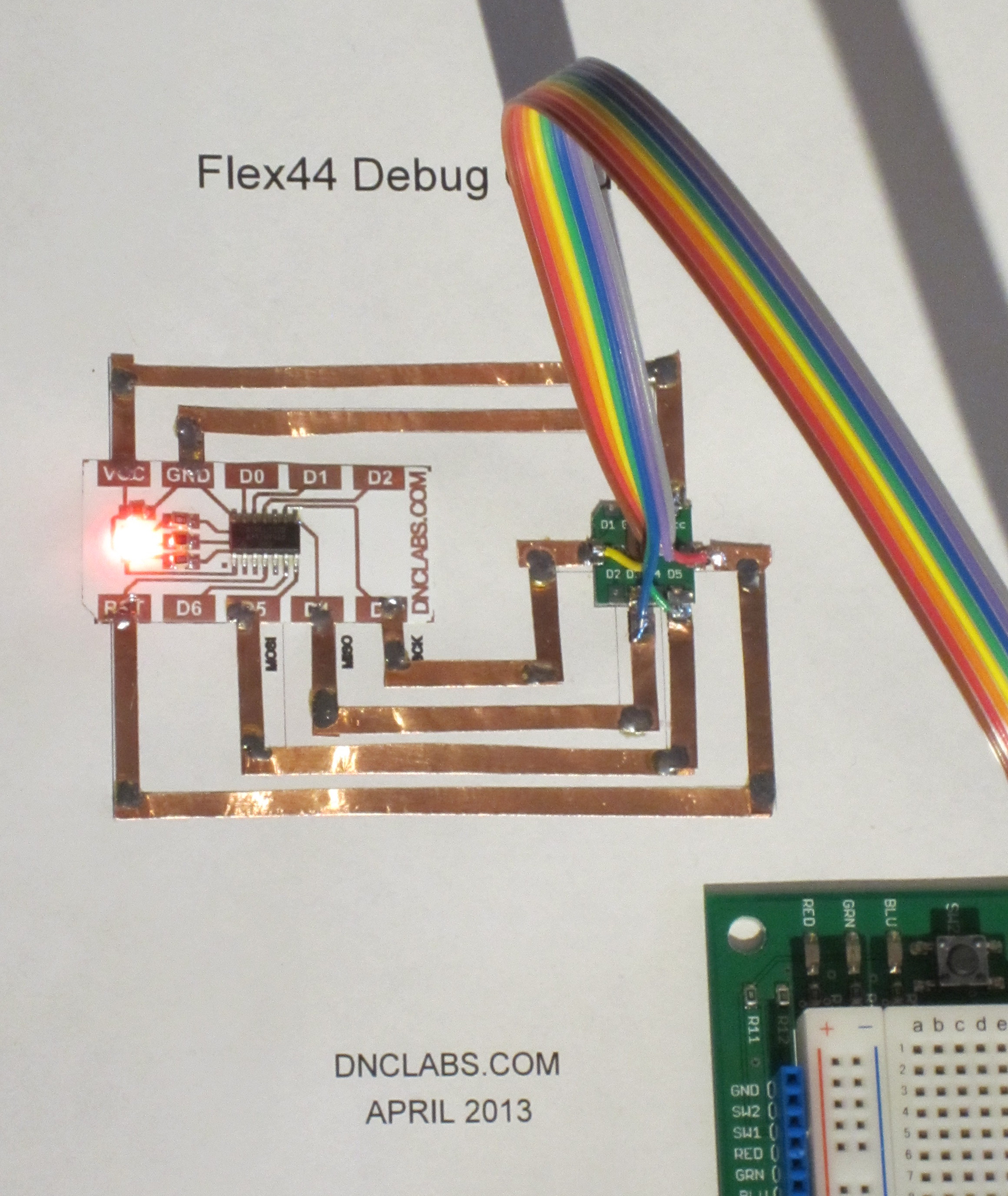
The initial soldering tests were less than promising but I have improved the results as I describe below. The test circuit shows the circuit in use along with a very ugly programming interface soldered to the paper circuit. I have a programmer on order as well that will hopefully simplify the design by eliminating the soldered wires. In the mean time I have been testing the circuit and creating an easy to use Arduino environment.
Issues
- finger prints on the foil rapidly corrode the copper which may create soldering issues.
- solder iron burns through the plastic making hand soldering difficult
- re-flow occurs at ~183C but at this temperature the plastic substrate starts to shrink and warp
Techniques
Soldering copper tape to flex circuit
It is possible to solder copper tape to the flex circuit but only if you keep the soldering temperature as low as possible. I found that by laying the copper tape over the flex foil circuit pad I could apply heat to the copper tape without damaging the flex circuit. I wet the copper tape with solder and then spill a small amount of solder over the edge of the copper tape onto the flex foil circuit pads. The copper tape acts as a heat sink and keeps the whole assembly from overheating.
Re-flow of flex circuit
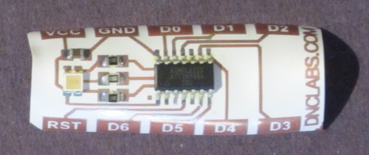 Direct re-flow of the flex foil circuit causes the plastic to curl down as the circuit reaches its re-flow temperature. The final circuit is severely distorted and it is not possible to flatten it out after soldering. On the up side the solder wets the flexible circuit nicely and the lack of solder mask is not an issue as the plastic performs this function.
Re-flow of flex circuit with paper backing
I glued the flex circuit down to a paper substrate using yellow PVA glue (wood glue) prior to re-flow soldering. The result was that the plastic did not distort however the whole assembly cupped down severely. The use of glue and paper also doubles the weight and stiffness of the assembly which limits the usefulness of this solution. Practically re-flowing larger pieces would be difficult because of the size of the re-flow oven. This technique is only really practical for small 4″x8″ pieces that fit in my toaster oven re-flow process.
Shielded re-flow
 I created a window box in cardboard to shield the plastic during re-flow and the result was very good except that the cardboard tends to cook a bit. The re-flow takes longer because of the additional thermal mass but re-flow times are still quick. The window box covers the top and bottom of the circuit and is held together with large binder clips to shield the plastic during re-flow.
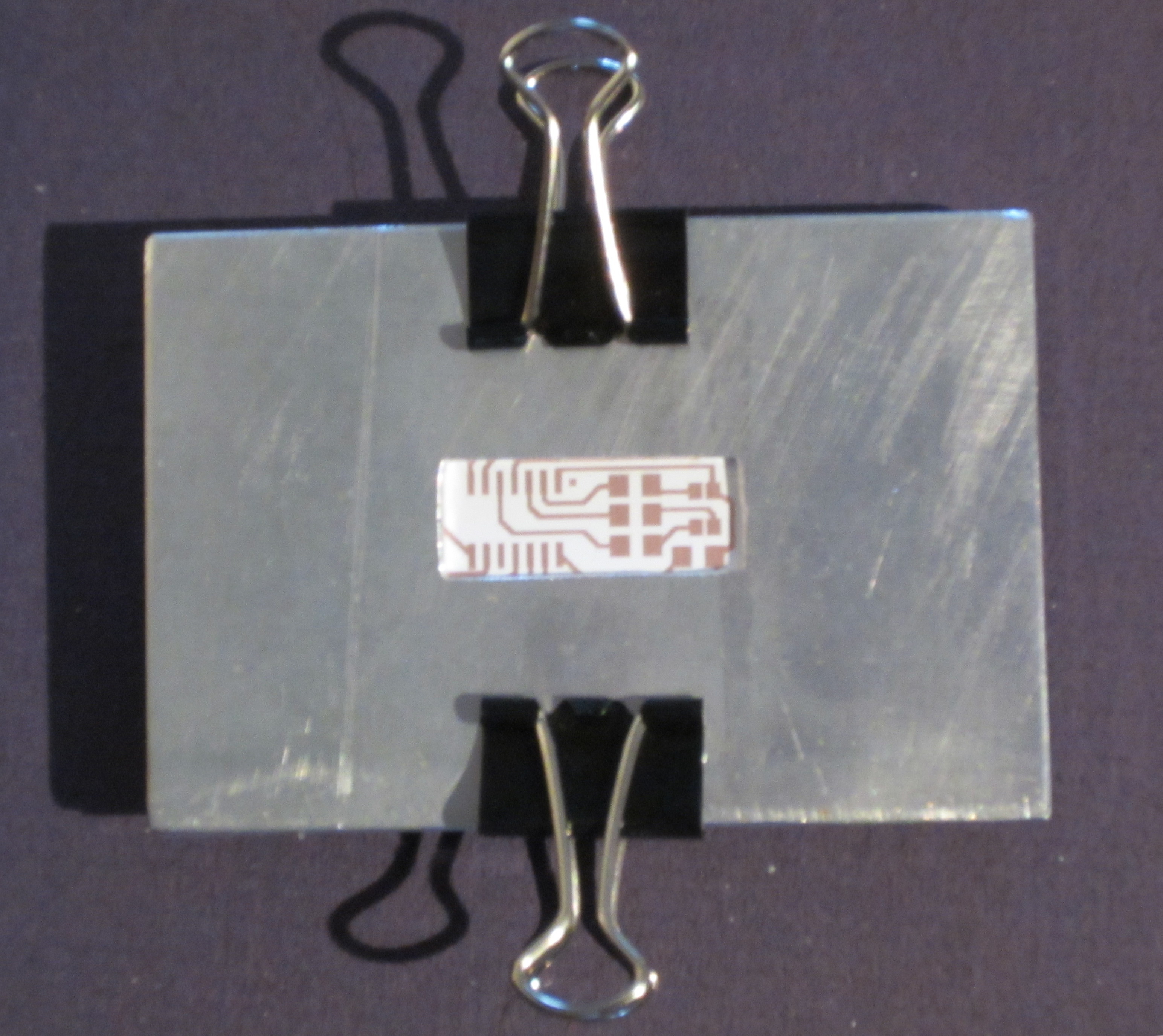
As a second attempt at the window box idea I tried an aluminium cover plate and support. This worked at keeping the PCB flat however the re-flow time and temperature were far to long. The oven could barely get the solder paste to re-flow. The thermal heat sink formed by the aluminium plates is to great. The extended re-flow time also made the plastic stick to the aluminium as it melted to the metal. Perhaps I could use an copper-less FR4 back plate.
Future Experiments
- Try tin bismuth solder which melts at 137C rather than 183C. http://www.qualitek.com/product_preview.html