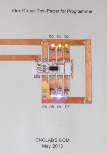
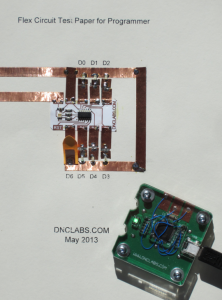
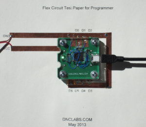
 I have received and built the in circuit version of the flex foil programmer and now have it working. There are a number of issues that I still want to improve on. The programmer consists of an AVR ISP programmer sitting on top of my own USB CDC library called Gecko. I described this in a Circuit Cellar article Jun 2011 Issue 251. I chose to use the AVR ISP programmer since that works seamlessly with Arduino sketch. The test circuit for the programmer is shown here complete with 6 LEDs and a paper switch.
My Gecko library worked with Windows 7, XP and Ubuntu however it gave me trouble with Mac OSX. Until recently I didn’t have access to a Mac computer to test the code. I finally traced down the problem to a “/” character in the USB serial number that cause the Mac to complain. That said; I now have the Gecko CDC library working with all major operating systems. The source code for the project can be found here. Gecko_library
 Using the programmer is very intuitive; you just plug in the programmer and it will start flashing red to indicate it has not detected a device to program. The programmer is placed over the flex foil using the optical guides to position the programmer over the circuit. Mill max spring loaded pins contact the flexible circuit pads to make a soft connection with the programmer. The programmer will begin to flash green when the connection is made. Finally while the programmer is flashing green you can download a sketch from the Arduino environment just like you would to program an Arduino Uno. The programmer flashes blue while the device is being programmed and returns to green once complete.
I have started my next design variant which is why there all of those blue wires in the current design. I am testing out a couple of improvements. The current design works for a single sided circuit but what happens when I design a double sided flex circuit that can be mounted right side up or down? I want this feature so that the flex circuit can be mounted in thin card board or behind it. Also although I have keyed the design so that pin 1 is obvious I’m not sure that my 5 year old volunteers will pay attention to that. There is a real risk that the programmer will be installed backwards causing the flex circuit to have the power and ground reversed, potentially damaging the Tiny44. The current design is equipped with 100 ohm resistors to limit the short circuit current and reduces the risk of frying the chip but I think I can do better.
The new programmer design will support auto detection of the power and ground pins on the flex foil. I have designed an algorithm that actively probes the Tiny44 target to determine which flex circuit pins are connected to which programmer pins. The design works by measuring the voltage drops across the ESD diodes inside the Tiny44. Once the orientation of the flex circuit to programmer is known I test to see if I can read the device signature. As a visual feed back the programmer pulses red until the device is actually detected at which point it pulses green.

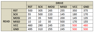
To detect the Tiny44 pin pattern I drive a test voltage of Vcc out of each of the programmer pins while monitoring the return leakage voltage on all of the other programmer pins. Since the probe voltage has no real return path to ground the Tiny44 will only see a few uA of current during the test which pretty much eliminates the risk of blowing the device up. The table below shows the results form such a probe. The corner values in red are the ones I look for. Notice that the ground pin is always ~20mV lower than Vcc when the circuit is driven from the Tiny44 power pins.
Finally I have found a supplier of affordable double sided polyimide flex circuit so I have designed a new flex foil circuit that is slightly smaller at 33x20mm. This new circuit will allow it to be mounted upside right or down. It also offers better solderability and the silk screen provides much better readability. Stay tuned…
