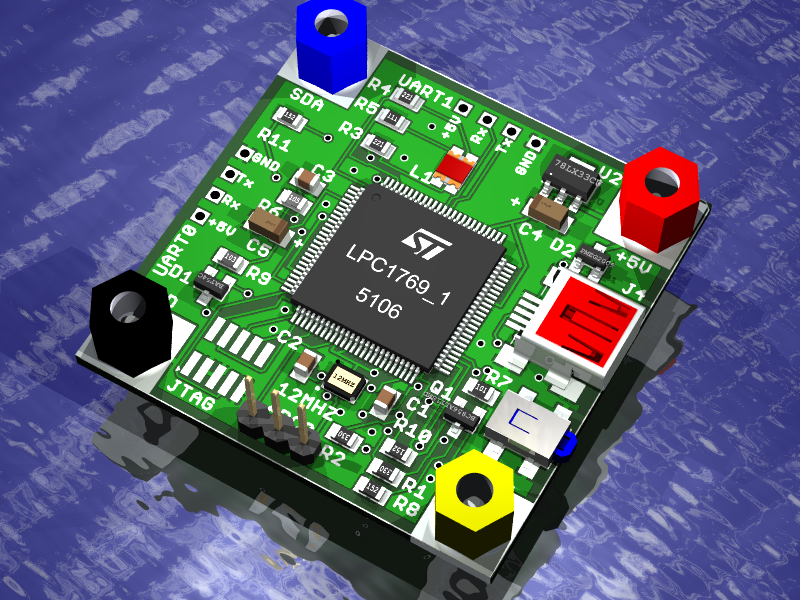
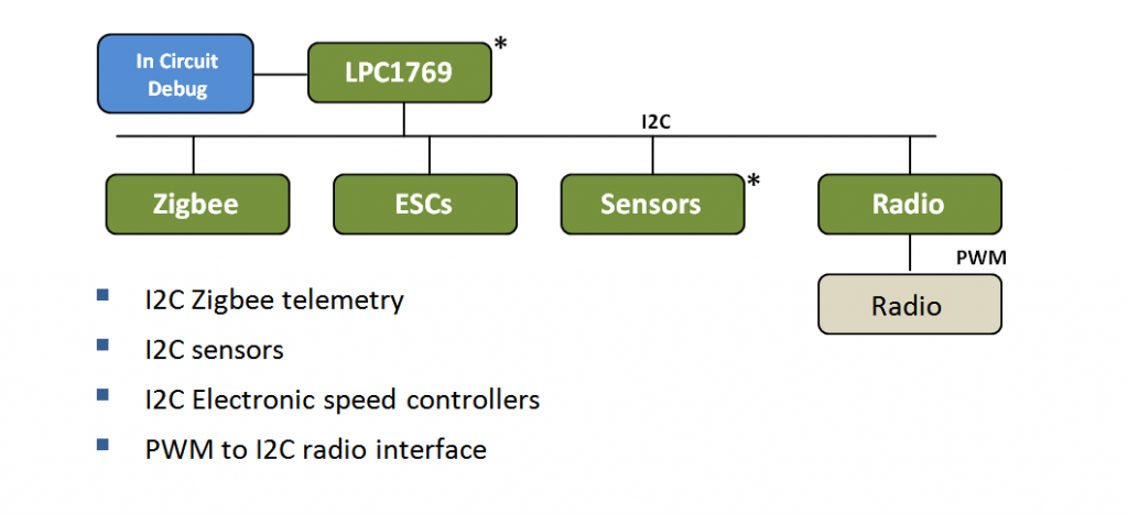
I have re-designed the hardware for the quadracopter, moving from the LPCExpresso board to a smaller purpose built board. The LPC1769 is designed to run on one PCB and controls all of the sensors located on a single daughter board. The processor board consists of the LPC1769 processor configured to run as a USB memory stick so that code can be directly loaded simply by copying it to the on board flash. All sensor and servo motor functions have been moved to a sensor daughter board. Communication between the micro controller and sensors is driven by the I2C bus. Physically 4 aluminum standoffs connect the boards and provide I2C and +5V power distribution so that multiple sensor boards can be connected.
The new design partition allows rapid development of new sensor boards. It also isolates hardware failures to lower cost replacement boards. When building the original LPCExpresso daughter card I had soldering issues with the magnetometer which meant that I had to scrap the entire board loosing all of the good sensors in the process. Moving the servo and radio functions to the daughter card means that I need another micro controller to manage the signals which at this stage may seem inefficient and costly. Moving forward I envision replacing the servo control with I2C brushless motor ESCs and the radio control will probably become a wireless Zigbee solution designed to support telemetry and control. The clean application interface of each module allows any function to be replaced or removed without requiring a re-design of the core quadracopter functions. The two new boards are marked with an asterisk.
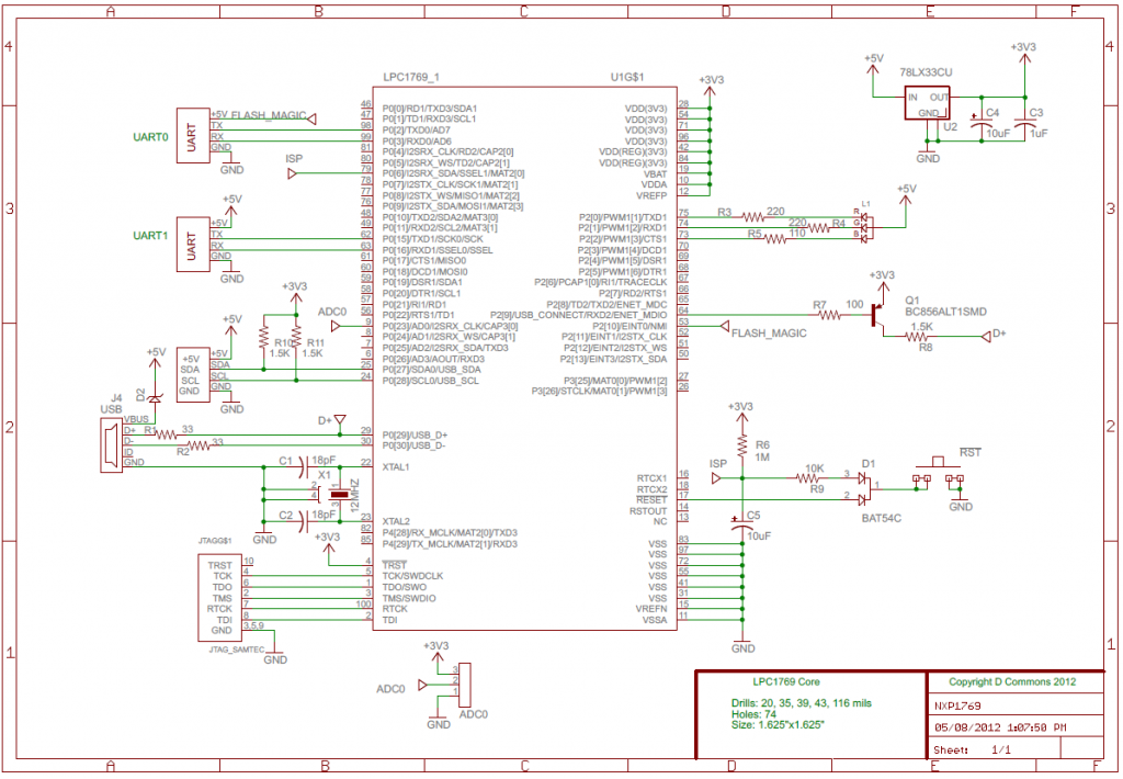
The LPC1769 core provides a compute platform for the quadracopter. To facilitate programming UART0 is brought to an I/O header so that code can be downloaded directly to the processor over a serial TTL link using Flash Magic. To place the LP1769 ROM firmware in the serial boot loader mode the FlashMagic signal on the schematic (NMI) is set high during reset. After the reset the chip responds to serial download commands over UART0. The intent of this feature is to allow you to download your first software image without requiring a programmer. For the quadracopter the first and only image loaded this way is a USB loader that allows you to plug the board into a USB port where the device is recognized as a Flash memory stick. To download a new code image you simply erase the memory stick and copy the new image to the device using Windows drag and drop. The reset button is set up with an RC time constant so that a brief button press results in a processor reset. If you press the reset button and hold it for longer that 2seconds then the ISP mode is engaged such that the USB Flash stick feature is enabled. Finally a 1mm JTAG header is provided to allow in circuit emulation and code download if you have an ICE. Note that I use the ICE that came with the LPCExpresso board. I cut off the target board and just use the ICE portion with my new hardware.
The LPC1769 talks to peripheral boards over I2C0 which is pulled up with 1.5K resistors to accommodate the heavy capacitive load which may be present if many boards are connected.
One ADC port is also broken out on the board to accommodate the test bed set up. The idea is to connect the test bed potentiometer to this ADC header so that the processor core can report the absolute angle of the test bed swing arm. Of course the potentiometer must be calibrated but I have written code to perform this as part of the test bed environment.
Schematic NXP1769_V1.2


1 comment for “New quadracopter hardware”