After the Maker Faire in September I set out to simplify my paper car design. Well simple is relative. I re-designed elements of the car to provide an easier to assemble, more robust design. The simplifications are designed to make it easier to use the car. I did this by pre-building as much of the design as possible and by hiding complexity behind simple user interfaces. Rather than rely on copper foil alone most of the circuitry is provided by an assembled PCB. Three design elements of the car were overhauled as part of this design improvement. The electronics was designed into a modular engine that can be re-used on a variety of different designs. The paper car body has also been redesigned so that it is faster to assemble and requires fewer steps and less laser cutting time. Finally the wheels were also re-designed so that they would be custom made from urethane rubber.
Engine
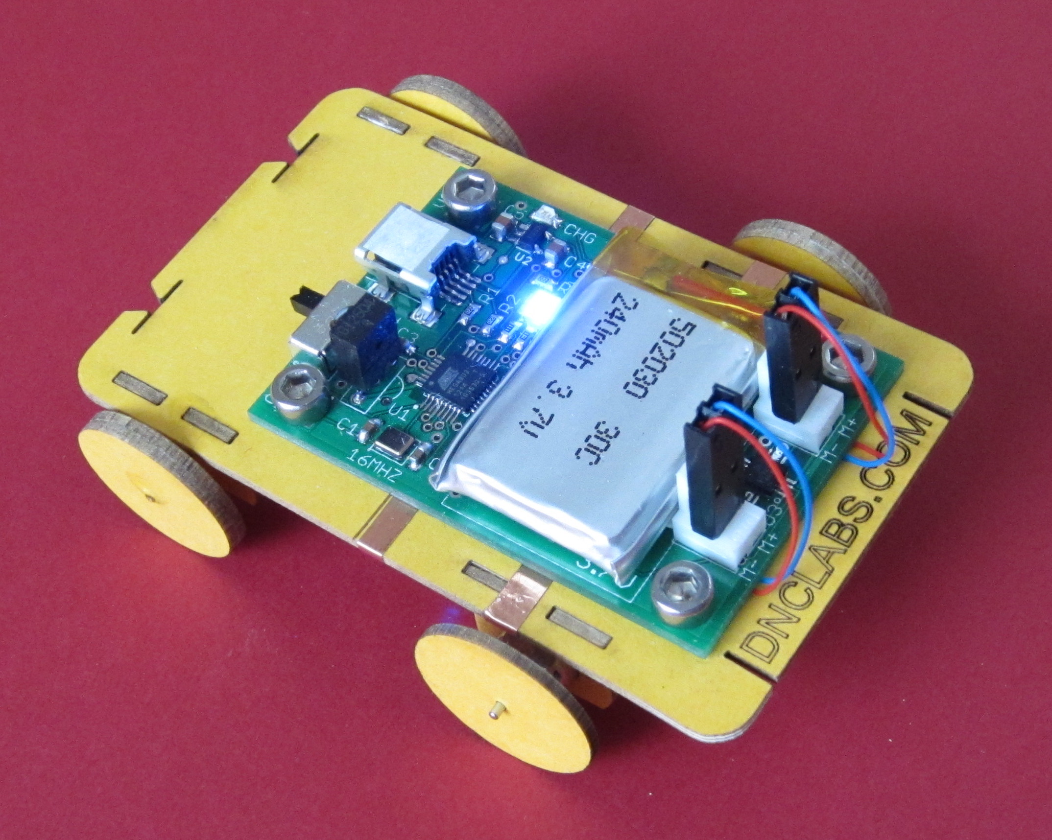
 I decided to totally re-design the electronics for the car to create a new engine block. The new design provides an ATMega8U2 processor which is USB programmable directly from Arduino sketch. To provide for better motor control I have included a dual H-bridge which allows the motor to be driven in either the forward or reverse direction. With a dual H-bridge each motor is individually controlled so that it is possible to have one motor turn forward while the other turns in reverse.
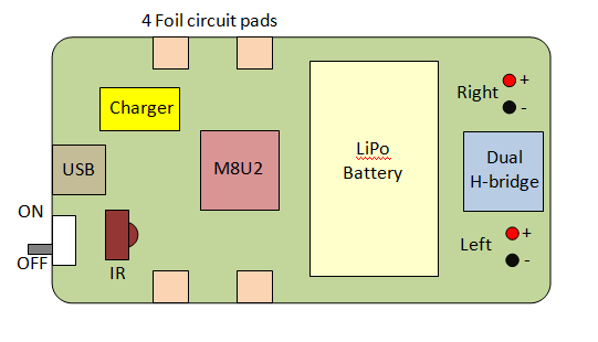
An infrared receiver was added so that the car can be remotely controlled with a standard TV remote control. The original AAA battery design was bulky and required periodic battery replacement when you drained the batteries. The new design provides a re-chargeable lithium polymer battery which is smaller and lighter. The battery is charged any time the USB cable is plugged in; for example, when programming the car. The original paper car used a jumper clip to turn the car on and off. The problem with the jumper was that it was to easy to loose making the car useless. To address this I have include a PCB mounted slide switch which is significantly more robust. Finally to maintain the flexibility of using copper foil to customize the design I included four PCB pads that are located on the bottom side of the PCB. When the PCB is bolted down to the cardboard body of a car the pads can directly connect to copper foil traces that are installed on the cardboard body. The block diagram of the board is shown below. The schematic is available here. Paper_Car_Engine.pdf
Software
The new engine required a significant amount of code development. First I needed to develop a USB bootloader so that I could download code to the M8U2. The bootloader allows me to write programs in Arduino sketch and download them directly to the processor. Currently I have a working version of the bootloader but I am still updating the code so that it is easier to use. Specifically I need the auto load feature to work without requiring me to manually reset the processor. For now its good enough for testing.
In addition to the loader I have also developed an IR interface and H bridge driver so that I can remotely control the engine. The total code space is just over 1K so there is plenty of room for customizations. The bootloader uses 4K of code but provides a serial CDC to your sketch which is very handy for debugging. The current design limits the application code size to 4K but this represents about 4 pages of C code which is a lot for someone just learning to code.
Body
 The body has been designed so that the engine bolts to the paper which allows the engine to be re-used. A few extra holes were required to allow for through hole pins sticking out the bottom of the PCB. The holes allow the PCB to lie flat on the paper which serves two purposes. First the PCB stiffens the car and second it provides pressure fit contacts to four I/O pads on the bottom of the PCB. I have etched construction lines to show where the copper tape needs to be placed. I have also added white LED head lights to the design. The LEDs are controlled by the I/O pads and copper foil circuit. This feature allows all sorts of custom options. As you can see I still included paper wheels but this is only a temporary measure.
Wheels
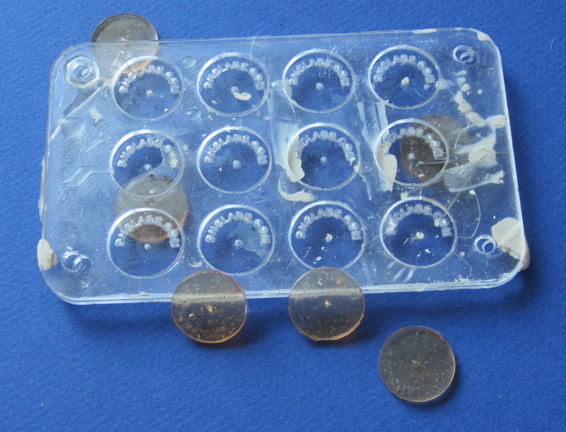
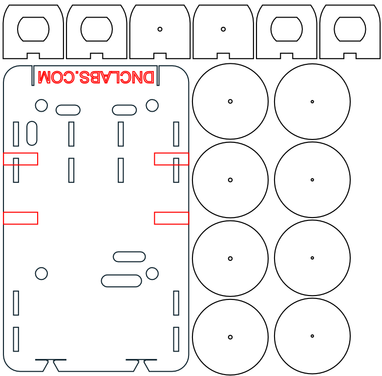
The original paper wheels work quite well but they eventually pull off and I wanted something a bit more robust. I chose to cast custom wheels out of urethane rubber. The mould templates were all laser cut out of acrylic. The wheels themselves have my web address etched into the design so that when cast the text becomes visible. The mould design shown here is 0.125″ thick but I will redesign it to be 0.25″ thick to provide better traction and a tighter fit to the motor shaft. The initial experiment resulted in faint text on the wheel because the lines were to fine. The next design will use a bold text font and deeper raster etched lettering.
Errata
This iteration of the design highlights a number of features that I want to enhance. The errata list is long but after using the current design for a few weeks I think these improvements would be a welcome addition.
- The board needs a polyfuse on the LiPo battery to keep user short circuits from burning out PCB traces.
- The board needs ESD protection on USB connector
- There is no Lipo protection from draining the battery below 3V which would kill it. I need to add under-voltage protection.
- I need “Left” and “Right” labels for motor connectors
- ISP connector is offset by ~1mm. It needs to be aligned to the programmer.
- Motor jumpers interfere with battery edge. I need to find a different connector. I am considering reverse entry connectors for the motors so that I can couple the motors directly though the car body.
- The IR detector is wire backwards in the symbol. The Vcc pin is on the far right when facing the domed receiver. Vout on the left.
- The contact pads are 0.125″ and I think 0.25″ would be better since that is the default copper tape width.
- Note that because of the plated through connectors I will need holes in the paper car template to allow the board to mount flat on the cardboard. I should eliminated as many plated through pads as possible ie) use SMT pads where possible. The LiPo battery connections should be SMT pads to keep the secondary side of the PCB flat.
- Rubber tires have too large a hole in the middle so they tend to slip. I also think that the tires need to be 0.25″ wide to provide more friction on the motor shaft.
- There may be a power surge issue with the motors turning on and off which causes the processor to reset. I may need to kill the BOD to keep the processor alive. I will also add a diode and capacitor to isolate the microprocessor from the motor noise.
- The VCC and GND pads need to extend to the board edge.
- I need a power led so that I can tell when the switch is on.