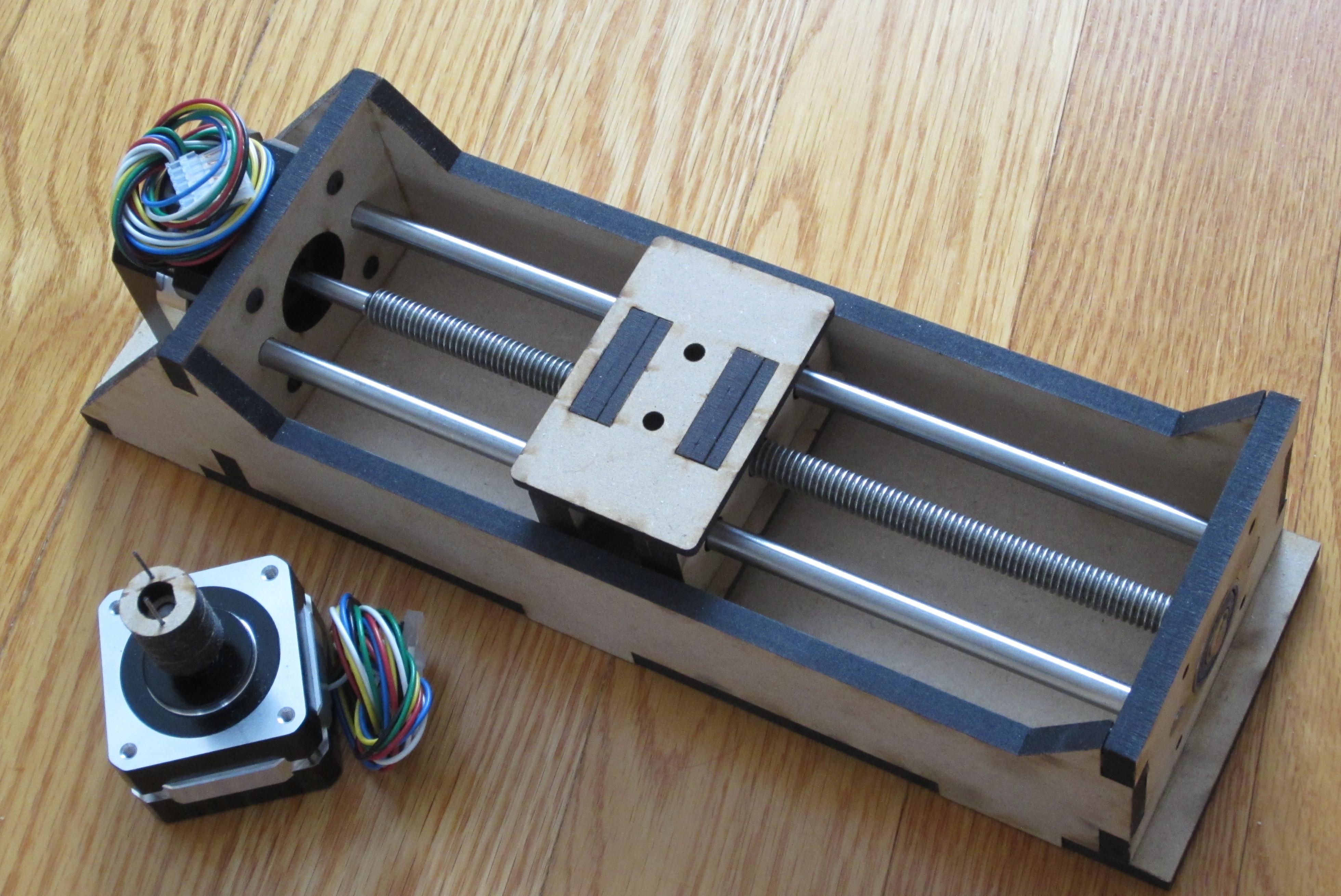
 I was trolling the web and came across a great deal on LM6U linear bearings ($0.50). I also managed to find six Nema 17 stepper motors for $20 delivered. So what am I going to do with these parts? I have decided to design a simple linear actuator to learn more about designing robotic machines. The linear actuator was designed to be laser cut from 1/4″ MDF so that the assembly and manufacture of parts is relatively simple. I designed the actuator to be easy to assemble while providing a relatively small 15cm movement. This first design doesn’t have end stops but I will add then. I would like to try a bit of a non-traditional solution for the end stops.
The connection of the threaded shaft to motor poses an interesting challenge. I want to counter bore the threaded shaft but I don’t have easy access to a metal lathe. To solve this issue I used the laser cut coupler that I described in my last post. The LM6U bearings run on a pair of 6mm steel drill rod rails while the lead screw is a 5/16″ threaded rod.
This design also includes a new Cortex M3 processor board for motor control. The design provides an isolated stepper controller that is controlled over a USB port. The board assembly manages thermal issues associated with the DRV8818 driver chip by providing an integrated heat sink. Current control is managed through a software interface which means there are no potentiometers to adjust. The USB software interface allows the user to select the drive current. This feature also means that the current can be adjusted dynamically when switching between full step and micro stepping modes.
Structurally the actuator uses braces to hold the assembly rigidly. The actuator uses a 3/4″ nut to reduce backlash by providing more tooth contact. The LM6U bearings come with impressive specifications but the reality is they have a few mils of play. To accommodate the unexpected play I will have to adjust the spacing of the linear rails to pre-tension the bearings and limit the play.
While laser cut MDF provides great cutting accuracy +-0.07mm; the laser kerf must be managed if you want the achieve a really tight fit. I accommodate for the kerf by cutting all holes -0.07mm smaller than the finished hole size. Similarly I make all tangs +0.07mm larger than the finished design size.
Electronics
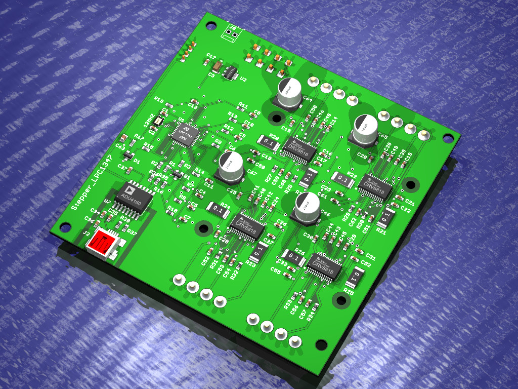 I was worried about the possibility of a motor short or inductive kick flowing back into my host PC. The results would be disastrous so I decided to isolate the stepper controller design; call it insurance. I use an ADU4160 controller to provide electrical isolation of the USB interface; this means that I have a 5kV isolation barrier between the motors and the host PC. The four stepper drivers are driven by a Cortex M3 processor. Unlike the typical Arduino design the ARM clocks in at 100MHz with a 32 bit data bus which allows me to run some very fast code. The board uses four DRV8818 drivers which are pretty standard but unlike most designs I have used the processor to generate the voltage references for the current and decay settings. The choice of software control of the current and decay modes means I can eliminate the typical potentiometers and replace them with a software tuning interface.
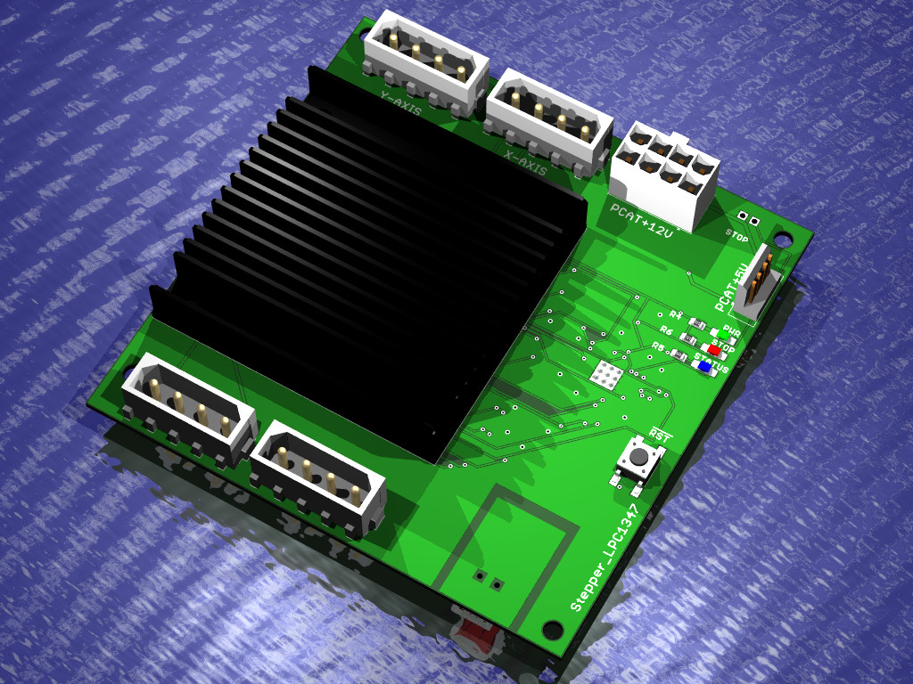 The second interesting detail of the stepper design is the integrated cooling system. If you look at a typical H-bridge drive it is equipped with a chip mounted heat sink which is not particularly effective. The thermal design of the DRV8818 is set-up to remove heat through the bottom of the die attached package. The best location for the heat sink is on the bottom of the chip so I totally re-worked the thermal design to take advantage of this. The PCB is laid out with thermal vias under the chip which conducts heat to a large 100x100mm heat sink on the secondary side of the board. I use a laser cut washer to electrically isolate the heat sink from the board and use thermal grease to provide a low resistance connection between the thermal vias and the heat sink.
Software
Currently the code running the stepper drivers consists of a simple on/off pulse train which is about as simple as it gets. The next step is to add acceleration control so that the motor speed ramps up and down without missing steps. The whole point of using a stepper motor is that it can be run open loop without any position feedback. This assumption is only valid if you don’t stall the motor which causes missed steps. The use of a second order acceleration control algorithm will go a long way to preventing stepping slips.
The other interesting detail about the stepper control design is that it allows dynamic control of the motor current. The typical potentiometer controlled stepper means you have to set the motor current once and hope it is optimal for all stepping operations. With direct control over the motor current I can tune the current to match the motor operation. I anticipate smoother and quieter motor operation and because I can reduce the current while idle I should also achieve cooler motor operation.
1 comment for “Linear Actuator Stepper”